Force and motion
Force and Motion
Discovering that a Circuit is not designed correctly
Circuit diagram showing a switch wired in parallel

The diagram above shows a switch wired in parallel. This was the cause of one of the troubleshooting issues in Lesson 2: the switch seems to work backwards. The problem is easy to detect using the circuit diagram above. When the switch is closed, it coneects the (+) side of the battery to the (-) side, creating a short circuit, which avoids the LED, so the LED doesn’t come on. Meanwhile, the battery heats up and drains quickly, because there is nothing in the circuit to abosrb its energy.
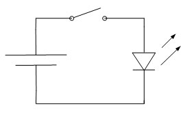
Circuit diagram showing a switch wired (correctly) in series

Here, the previous circuit diagram has been changed to put the switch in the proper path. When it is open, the switch will now interrupt the flow of current, which will cause the LED to turn on. When the switch is closed, it will connect the LED to the battery. and make it come on.